Abstract
This report presents a detailed technical analysis of designing a plant tray using SolidWorks, guided by Design for Manufacturing (DFM) principles for injection molding. The tray is intended for agricultural and nursery applications, where strength, durability, and cost efficiency are critical.
Key DFM factors such as wall thickness, draft angles, rib and boss design, ejector pin placement, gate and runner configuration, and material shrinkage are carefully evaluated. Real-world comparisons between inefficient and optimized designs highlight their impact on manufacturability and production cost.
The report also outlines a structured SolidWorks workflow, concluding with insights into manufacturing efficiency, cost optimization, and recommendations for scalable mass production.
Introduction to DFM and Injection Molding
Design for Manufacturing (DFM) is an engineering approach that ensures products are designed for easy, reliable, and cost-effective production without compromising functionality.
Injection molding is one of the most widely used processes for manufacturing plastic components due to its ability to produce large volumes with consistent quality and low per-unit cost. However, poor design can lead to defects such as:
- Sink marks
- Warpage
- Weld lines
- Extended cycle times
Applying DFM principles early in the design stage helps prevent these issues. Key considerations include:
- Maintaining uniform wall thickness
- Adding proper draft angles for easy ejection
- Avoiding sharp corners
- Optimizing gate and runner placement
- Using ribs for structural reinforcement
By incorporating these principles in SolidWorks, designers can reduce tooling complexity, minimize waste, and extend mold life.
Plant Tray Design Requirements
The plant tray is designed to hold multiple pots and is commonly used in nurseries and agricultural setups. Its design must meet the following requirements:
- Strength: Capable of supporting multiple filled pots
- Durability: Resistant to cracks, repeated use, and UV exposure
- Efficient drainage: Integrated cutouts to prevent water accumulation
- Stackability: Easy nesting for storage and transport
- Lightweight structure: Reduced handling and shipping costs
- Ease of manufacturing: Free from undercuts and optimized for fast production cycles
DFM ensures these functional needs are achieved without increasing production complexity.
Material Selection and Shrinkage
Material choice plays a crucial role in both performance and manufacturability. Common options include:
- Polypropylene (PP):High flexibility and toughness
- Good chemical resistance
- UV stabilizer compatibility
- Shrinkage: ~1.0–1.5%
- High-Density Polyethylene (HDPE):Higher stiffness and impact resistance
- Suitable for heavier loads
- Shrinkage: ~1.5–1.8%
Proper shrinkage allowances must be incorporated into the design to ensure dimensional accuracy.
Wall Thickness and Draft Angles
Uniform wall thickness is essential for preventing defects and ensuring efficient cooling.
- Recommended thickness: 2.0–2.5 mm
- Balances durability and cooling efficiency
- Reduces risk of sink marks and warping
Draft angles of 1.5°–2° are applied to all vertical surfaces to facilitate smooth ejection. SolidWorks draft analysis tools are used to validate these parameters.
Ribs, Bosses, and Structural Features
Ribs are used to improve strength without increasing material usage. Standard DFM guidelines include:
- Rib thickness: 50% of wall thickness
- Rib height: 2–3× wall thickness
- Fillet radius: 0.25–0.5× rib thickness
Bosses serve as locating and fastening features. In this design, they also function as drainage holes. For example, a 10 mm pin fit requires a 10.1–10.2 mm hole to account for material shrinkage.
Fillets and Flow Optimization
Sharp corners are avoided to minimize stress concentration and improve material flow. Fillets with radii of 0.5–1 mm are applied at intersections.
Simulation in SolidWorks shows that adding fillets improves flow consistency and reduces defects. For instance, introducing a 0.8 mm fillet at a rib-wall junction eliminated weld line formation observed in earlier designs.
Ejector Pin Placement and Mold Design
Ejector pins are essential for removing the part from the mold. Best practices include:
- Positioning pins on non-visible surfaces
- Placing them near rib bases or thicker sections
- Distributing them evenly to prevent deformation
In this design, ejector pins are strategically located under reinforced areas to ensure smooth ejection without visible marks.
Gate and Runner Design
Proper gate and runner placement ensures balanced material flow and consistent part quality.
- Edge gates are placed near thicker rib sections
- Balanced runner systems distribute material evenly
- Minimizes flow hesitation and defects
Drainage and Stackability Features
Drainage holes are incorporated to prevent water accumulation and are designed with proper draft angles for easy molding.
Stackability is achieved through geometric nesting, allowing trays to be efficiently stored and transported. SolidWorks assembly testing confirms interference-free stacking.
SolidWorks Design Workflow
Concept Development
- Initial design created based on customer sketches
- Two pot models evaluated; HP5181 selected
- First prototype designed to hold 8 pots
Feedback and Optimization
- Initial design weight: 600 grams
- Customer requested reduced weight and height
- Alternative shallow design proposed
Final Design (Concept 2)
- Competitive market analysis conducted
- Weight reduced from 600 g to 130 g
- Approved by customer after review
- Final DFM features incorporated for manufacturing readiness
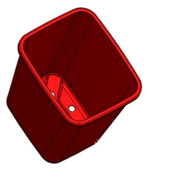
Design Summary
Base tray created using a rectangular sketch
Drainage cutouts added for weight reduction
Layout aligned with customer requirements
Ribs added using SolidWorks rib tool with draft
Fillets applied to internal edges
Shell tool used to reduce weight
Thickness analysis performed to ensure uniformity
DFM Validation and Mold Flow Analysis
Mold flow simulations are used to analyze:
- Material flow patterns
- Cooling efficiency
- Shrinkage behavior
- Potential defects such as weld lines and air traps
These insights help refine the design before tooling begins, saving time and cost.
Cost and Manufacturing Efficiency
DFM plays a major role in reducing production costs:
- Lower tooling cost: Simplified mold design
- Reduced cycle time: ~30–40 seconds per tray
- Optimized material usage: Ribs replace thick sections
- Improved tool life: Efficient ejection reduces wear
Conclusion
This study demonstrates how SolidWorks combined with DFM principles can produce a durable, lightweight, and cost-effective plant tray optimized for injection molding.
By carefully designing wall thickness, ribs, draft angles, fillets, and gating systems, manufacturers can significantly reduce defects and production costs.
DFM is not just a design approach—it is a strategic advantage for achieving efficiency and scalability in high-volume manufacturing.
Future improvements may include automated tray nesting systems and advanced cooling channel optimization for even better performance.