
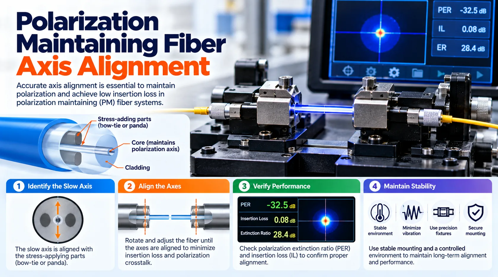
Polarization Maintaining Fiber Axis Alignment Systems are precision tools that find the internal stress axes of PM fiber and turn the fiber so its slow or fast axis lands at a set angle before fusion splicing or connector termination. By matching those two perpendicular axes closely, the equipment limits how much optical power leaks into the unwanted polarization mode. The payoff is a higher polarization extinction ratio (PER), which demanding builds such as fiber lasers, fiber-optic gyroscopes, and interferometric sensors typically rely on.
From the outside, PM fiber looks much like ordinary single-mode fiber, yet its value depends on how carefully its axes are handled at every joint. A splice or connector that sits a few degrees off can quietly undo the polarization control the fiber was made to provide. Knowing how alignment equipment works, and where it matters most, helps engineers and buyers set realistic tolerances before a lab bench or production line is built.
What Polarization Maintaining Fiber Axis Alignment Systems Do
At the simplest level, this equipment answers one question: where is the slow axis, and how far does the fiber need to turn to reach its target angle? Most designs pair a magnified camera view of the fiber with a rotation stage that can turn it through a full circle, plus software or a readout that reports the angle. Once the axis sits where it should, the fiber moves on to fusion splicing, epoxy curing, or another fixing step.
The same job shows up in two main settings. In PM fiber splicing, the axes of two fibers must match each other, while in connectorization the axis must match the connector key. Both depend on accurate polarization alignment, since an angle error locked in by a splice or by cured adhesive usually cannot be fixed without redoing the joint.
The Slow Axis, the Fast Axis, and Birefringence
Polarization-maintaining fiber is built with strong birefringence on purpose, so light polarized along one internal direction travels at a slightly different speed than light polarized along the perpendicular direction. Those two directions are known as the slow axis and the fast axis. When linearly polarized light is launched along either one, the fiber tends to hold that polarization even when it is bent.
The catch is that birefringence only helps when the light and the axes line up. If polarized light enters at an angle, part of the power lands on the other axis from the very start, and the fiber simply carries both parts forward. That is why the polarization maintaining fiber slow axis is the usual reference point for alignment work, since many PM connectors and components are specified around it.
Common PM Fiber Designs
Most PM fibers get their birefringence from stress-applying parts, which are zones of different glass placed on either side of the core. According to the RP Photonics Encyclopedia, these stress elements are typically made from boron-doped glass with a different rate of thermal expansion than the surrounding silica. The shape of those zones is exactly what alignment cameras look for, so fiber type has a direct effect on how easily the axis can be found.
Three stress-based designs and one shape-based design come up most often. Each one gives the alignment system a slightly different picture to read, which is why equipment specifications usually list the fiber types they support. The main families are summarized below.
- PANDA fiber: two round stress rods sit on opposite sides of the core and show up as dark "eyes" in an end view.
- Bow-tie fiber: wedge-shaped stress zones reach closer to the core, which can produce stronger birefringence.
- Elliptical stress-layer fiber: an oval cladding layer of different glass surrounds the core.
- Elliptical-core fiber: birefringence comes from the oval shape of the core itself (form birefringence) rather than from added stress.
Why Small Angle Errors Have Large Effects
PER compares the optical power on the intended axis with the power that has crossed over to the other axis, and it is expressed in decibels. A PER of 30 dB, for example, means the wanted polarization carries roughly 1,000 times more power than the unwanted one. The leaked power is often called polarization crosstalk, and IEC test documents treat the two terms as closely linked.
Angular misalignment is one of the most direct sources of crosstalk at a joint. A widely used geometric estimate ties the misalignment angle (θ) to the best reachable PER through the expression PER ≈ −10·log10(tan²θ). The figures below come straight from that formula, so they describe a theoretical ceiling set by angle alone, before stress, contamination, or fiber quality are counted.
Angle Error Compared With the PER Ceiling
Axis misalignmentApproximate PER ceiling (angle only)0.5°about 41 dB1°about 35 dB2°about 29 dB3°about 26 dB5°about 21 dBValues calculated from PER ≈ −10·log10(tan²θ); real-world results are usually lower.
The pattern is easy to read: each added degree of error takes a clear bite out of the ceiling, and the drop is steepest across the first few degrees. A product with a 30 dB PER target leaves room for a little under 2° of axis error at a single joint, and less once other effects are included. Because every joint in a link adds its own error, builds with several splices or connectors often need tighter limits per joint than a one-joint calculation suggests.
This helps explain why the RP Photonics Encyclopedia describes PM fusion splicers as often aligning axes to better than 0.5°. At that level, angle error alone would typically sit above 40 dB, leaving headroom for fiber quality and handling. Vision-assisted connector benches with an on-screen angle readout are often described as holding about one degree in trained hands, which lines up with a theoretical ceiling near 35 dB.
Why Misalignment Often Goes Unnoticed
A misaligned PM joint still passes light, so a basic insertion loss check with a light source and power meter may show nothing unusual. The problem only surfaces when the polarization state is measured, usually with a polarized source and a PER meter or polarimeter. In plain terms, a cord can pass a routine continuity test while failing at the one job it was built for.
RP Photonics also points out that mechanical stress, including stress inside a fiber connector, can increase mixing between the two polarization modes. So alignment is only part of the story, since adhesive curing, crimping, and cable handling can lower PER after the angle has already been set. Sound production practice treats PER as something to verify after assembly, not only something to aim for at the alignment stage.
Planning PM splicing or termination work? Before comparing equipment, write down three numbers: your PER target, the fiber types involved, and your expected daily volume. Those figures narrow the choice of alignment method much faster than a feature list.
How Polarization Maintaining Fiber Axis Alignment Systems Locate the Axis
Equipment generally finds the axis in one of two ways. Passive methods read the fiber's internal structure from images, while active methods send polarized light through the fiber and rotate it until a PER reading peaks. Published research on automated fusion splicing of PM fibers describes image-based alignment that works without a light source at the far end, and it also covers how the result can be estimated before and after the splice.
Neither approach is best for every job. Image-based alignment is quick and does not need access to both fiber ends, which suits connector benches and most splicing work. Active alignment needs a polarized source and a meter hooked up to the fiber, but it measures the real optical result instead of inferring it from geometry.
End-View and Side-View Imaging
End-view systems look straight at the cleaved fiber face, where PANDA stress rods appear as two dark circles beside the core. The line running through those circles marks the slow axis, so the operator or the software turns the fiber until that line reaches the target angle. A panda eye alignment machine is one example of this method, pairing a magnified end-view camera with a live angle display.
Side-view methods, found in many PM fusion splicers, image the fiber from the side as it rotates and analyze how the stress zones change the brightness pattern. Since the fiber stays clamped in the splicer, side-view imaging lets polarization maintaining fiber alignment happen just before the arc fires. Each method has strengths and limits with certain fiber types, so buyers usually check which designs a system has been validated on.
Active Alignment With a PER Meter
In active alignment, a highly polarized source feeds one fiber, a PER meter reads the output of the other, and one fiber end rotates until the measured ratio reaches its peak. Patent literature on PM fiber alignment describes this active method alongside passive, image-based alignment carried out at the splice point. Its main strength is that the reading reflects how the joint actually behaves with polarized light.
The drawbacks are mostly practical. Both fiber ends need to be reachable and connected to test gear, which is rarely convenient for long installed runs or for fiber already built into a device. For that reason, active alignment tends to appear in labs, component manufacturing, and qualification testing more often than in routine field work.
Alignment During Splicing Compared With Connectorization
During PM fiber splicing, two fibers are rotated so their slow axes match, or so they sit at a deliberate offset such as 45° or 90° when a device design calls for it. Polarization Maintaining Fiber Axis Alignment Systems inside PM splicers handle that rotation and hold the angle while the arc fuses the fibers. Splice loss still counts, but in PM work the angle between the axes is often the figure that decides pass or fail.
Connectorization brings in a different reference point, which is the connector key. By common convention, noted for FC/APC connectors in the RP Photonics Encyclopedia, the slow axis is aligned with the key so two mated connectors keep their axes matched. After alignment, the fiber is usually bonded in the ferrule, and heat curing in a fiber optic curing oven sets the adhesive, which is why steady, even curing supports stable PER results.
Where Accurate Polarization Alignment Matters Most
PM fiber is chosen where the polarization state cannot be allowed to wander. The RP Photonics Encyclopedia names fiber interferometers, fiber-optic gyroscopes, and certain fiber lasers as typical examples. In each case, poor alignment at a single joint can show up as drift, noise, or reduced output stability in the finished system.
Common application areas are listed below, though exact PER needs vary widely by design. Engineers generally set joint tolerances by working backward from the overall polarization budget of the system. That budget then guides how much angle error each splice or connector is allowed to add.
- Fiber-optic gyroscopes, where stable polarization supports steady interference between light traveling in opposite directions around a coil.
- Fiber lasers and amplifiers that need a linearly polarized output.
- Interferometric and polarimetric sensors used in measurement and monitoring.
- PM-pigtailed components, such as couplers, isolators, and modulators, where each pigtail joint adds its own alignment error.
How to Choose an Alignment Approach
The right setup depends mostly on volume, fiber types, and the PER the finished product has to meet. Manual or vision-assisted benches often suit labs, repair work, and low-volume lines, since a trained operator can reach good results at modest cost. Higher volumes and tighter PER targets usually favor automated equipment, which reduces reliance on the skill of any single operator.
Automation mainly adds repeatability. An automatic polarization maintaining fiber alignment system detects the stress-applying parts and drives the rotation itself, which helps keep results consistent across shifts. When Polarization Maintaining Fiber Axis Alignment Systems also record the final angle for each part, that record can support traceability during quality audits.
Useful questions to raise with any equipment supplier include:
- Which PM fiber types (PANDA, bow-tie, elliptical) has the system been validated on?
- What angular accuracy is specified, and how was it measured?
- Can it set offset angles such as 45° or 90°, not just 0°?
- Which connector types and ferrule holders are supported?
- Can sample parts be aligned and PER-tested on your own fiber before purchase?
Good Practices That Protect Alignment Quality
Alignment quality starts before the fiber ever reaches the camera. A clean, flat cleave gives end-view systems a clear picture of the stress rods, while dust or chips on the end face can confuse both operators and software. Careful stripping and handling help as well, because nicks and twists add stress that can shift results after alignment.
Final checks close the loop. IEC 61300-3-55:2020 sets out methods for measuring the PER of single-mode PM components, giving makers and buyers a shared reference for test results. Testing a sample of finished parts this way helps confirm that the angle set during alignment survived curing, polishing, and assembly.
- Inspect and clean end faces before imaging the fiber.
- Confirm the target angle and key reference for each job before rotating.
- Measure PER on finished parts, not only at the alignment stage.
- Log results over time to spot slow drift in the process.
Building a Reliable PM Alignment Process
Accurate axis alignment is what lets PM fiber deliver the polarization control it is bought for. The fiber design, the alignment method, the fixing step, and the final PER test all work together, and a weak point in any one of them can pull results down. Teams that treat alignment as part of a measured process, instead of a single machine setting, generally see more consistent output.
If a PM project is coming up, start by defining your PER target, fiber types, and expected volume. Then request sample alignments on your own fiber and review the PER data before committing to any equipment. A short conversation with an alignment equipment engineer at that stage can clarify which method fits the job and prevent costly rework later.
Frequently Asked Questions
What are polarization maintaining fiber axis alignment systems used for?
They are used to rotate PM fiber so its stress axes sit at a precise angle before splicing or connector termination. This keeps polarized light on the intended axis and protects the extinction ratio of the finished joint. Labs, component makers, and PM patch cord producers are among the most common users.
What is the slow axis in PM fiber?
The slow axis is the internal direction along which polarized light travels slightly more slowly because of the fiber's built-in birefringence. In PANDA fiber, it runs through the two stress rods on either side of the core. By common convention, many PM connectors align this axis with the connector key.
What is a good polarization extinction ratio for PM connectors?
A good PER is one that meets the polarization budget of the specific system, so there is no single universal figure. Values in the 20 to 30 dB range and higher are commonly quoted for PM splices and connectors. Interferometric and sensing builds may call for stricter targets, so specifications are best taken from the system design.
How accurate does PM axis alignment need to be?
Required accuracy depends on the PER target, since angle error alone caps the best reachable ratio. Using the common geometric estimate, about 1.8° of error limits a joint to roughly 30 dB, while about 0.5° allows around 41 dB. Real results are usually a little lower once stress and handling effects are added.
Can a standard fusion splicer join PM fiber?
A standard splicer can fuse PM fiber physically, but it typically lacks the axis detection and rotation needed to match the stress axes. Without that step, the splice may show low loss while delivering poor PER. PM work is generally done on splicers built with rotating fiber holders and polarization alignment software.
What is the difference between PANDA and bow-tie fiber?
Both are stress-based PM fibers, and the difference lies in the shape of their stress-applying parts. PANDA fiber uses two round rods, while bow-tie fiber uses wedge-shaped zones that reach closer to the core. Bow-tie designs can produce stronger birefringence, and both types can be aligned with suitable imaging equipment.
How is polarization extinction ratio measured?
PER is measured by launching polarized light into the fiber and comparing the maximum and minimum power seen through a rotating polarizer at the output. The ratio of those two readings, expressed in decibels, gives the PER. IEC 61300-3-55:2020 describes standardized methods for PM components.
Why can PER drop after a PM connector is assembled?
PER can drop after assembly because mechanical stress in the connector can mix power between the two polarization modes. Adhesive shrinkage during curing, polishing pressure, and tight cable handling are typical contributors. Measuring PER on finished connectors, not only during alignment, helps catch these losses early.