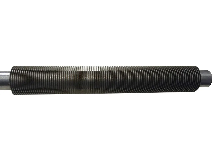

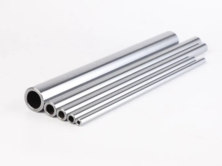
Hollow shafts represent an elegant engineering solution to one of the oldest challenges in mechanical design: how to maximize torsional stiffness while minimizing weight. By removing material from the center of a shaft—where it contributes least to bending and torsional resistance—engineers can achieve dramatic weight reductions without sacrificing performance. In industries ranging from electric motors to aerospace actuators, hollow shafts have become the component of choice for applications demanding high power density, internal routing of fluids or wiring, and compact envelope dimensions. Wuxi Xinluo Hydraulic manufactures precision hollow shafts for hydraulic, pneumatic, and electromechanical systems, combining deep metallurgical expertise with modern manufacturing processes to deliver components that meet the most rigorous specifications.
What Is a Hollow Shaft?
A hollow shaft is a cylindrical rotating or structural element with a through-hole along its longitudinal axis. Unlike a solid (solid-section) shaft, the hollow shaft removes material from the central region, creating a tubular cross-section. This design leverages a fundamental principle of mechanics: in torsion and bending, the stress is highest at the outer surface and decreases toward the center. Material near the neutral axis contributes relatively little to load-bearing capacity, so its removal yields significant weight savings with only marginal reduction in strength.
Hollow shafts are used across an enormous range of applications—from the drive shafts in automotive transmissions to the rotor shafts in electric motors, from machine tool spindles to hydraulic cylinder piston rods. In many cases, the internal bore serves a dual purpose: it reduces weight while also providing a passage for coolant, hydraulic fluid, electrical cables, or sensor wiring.
Classification by Application
Motor shafts: Rotor shafts in electric motors and generators, often requiring precision bearing seats and keyways.
Hydraulic piston rods: Hollow rods used in double-rod cylinders or as displacement rods in plunger-type actuators.
Drive shafts: Power transmission elements in gearboxes, couplings, and universal joint assemblies.
Instrumentation shafts: Lightweight shafts for encoders, resolvers, and other feedback devices.
Technical Specifications and StandardsThe engineering value of a hollow shaft is quantified through its geometric properties—specifically the ratio of outer diameter (OD) to inner diameter (ID), commonly expressed as the diameter ratio (k = ID/OD).
Weight Reduction Analysis
For a solid shaft of diameter D, the polar moment of inertia is J = πD⁴/32. For a hollow shaft with outer diameter D and inner diameter d, the polar moment of inertia is J = π(D⁴ - d⁴)/32. By selecting appropriate OD and ID values, engineers can maintain the required torsional rigidity while removing 30–50% of the cross-sectional area—and therefore 30–50% of the weight—compared to a solid shaft of equivalent torsional stiffness.
For example, a hollow shaft with k = 0.7 (ID = 70% of OD) retains approximately 76% of the torsional rigidity of a solid shaft of the same OD but weighs only about 51% as much. This represents a stiffness-to-weight ratio improvement of roughly 49%.
Material Selection
Common materials for hollow shafts include:
Medium-carbon steel (45# / S45C / C45): General-purpose applications, suitable for induction hardening.
Alloy steel (42CrMo / SCM440 / 4140): High-strength applications requiring through-hardening or case hardening.
Stainless steel (SUS304 / SUS316 / 17-4PH): Corrosive environments or food/medical-grade applications.
Aluminum alloy (6061-T6 / 7075-T6): Aerospace and high-speed rotational applications where weight is paramount.
Dimensional Standards
Hollow shafts are manufactured to various international standards depending on the application:
ISO 286 for general tolerance (IT6–IT8 for bearing seats).
ISO 14 for limits and fits on the bore.
DIN 748 for automotive drive shaft dimensions.
NEMA / IEC standards for motor shaft extensions.
Tolerances and Surface Finish
Bearing journal diameters typically require IT5–IT6 tolerance with surface finish Ra 0.4–0.8 µm. The outer cylindrical surface may be ground, polished, or chrome-plated depending on the application. Internal bore tolerances are generally IT8–IT10 unless the bore serves as a precision hydraulic seal surface.
Manufacturing ProcessProducing a hollow shaft involves several distinct operations, each selected based on the shaft's dimensions, material, and application requirements.
Step 1: Blank Preparation
The starting material is typically a hollow tube (seamless or cold-drawn) or a solid billet that will be drilled. For smaller diameters (OD < 60 mm), seamless steel tube is the most economical starting point. For larger shafts or those requiring precise concentricity between bore and OD, solid bar stock is deep-hole drilled.
Step 2: Machining
CNC turning creates the external profiles—bearing seats, shoulders, keyways, and threaded ends. For internal features, boring bars or gun drills achieve the required bore diameter. Cross-holes for oil passages or set screws are added via CNC milling or drilling.
Step 3: Heat Treatment
Depending on material and application, heat treatment may involve through-hardening, case hardening (induction or carburizing), or precipitation hardening. For hollow shafts, careful control prevents distortion due to thin-wall geometry.
Step 4: Finishing
The outer bearing surfaces are ground to final tolerance. Internal bores that serve as seal surfaces may be honed. Surface treatments such as chrome plating, nitriding, or DLC coating can be applied to improve wear and corrosion resistance.
Step 5: Inspection
Critical parameters—OD/ID diameter, concentricity, wall thickness, straightness, surface roughness, and hardness—are verified using CMM, bore gauges, ultrasonic testers, and hardness testers.
Applications and AdvantagesElectric Motors and Generators
In modern electric motors, especially EV powertrains and industrial servo drives, hollow shafts enable internal coolant circulation and wiring routing, eliminating external hoses and cable carriers.
Hydraulic and Pneumatic Cylinders
Hollow piston rods serve as displacement rods in single-acting cylinders and as conduits for sensing cables in smart cylinders. Weight reduction allows faster cycle times, especially in vertical applications.
Robotics and Automation
Robot joint shafts benefit from hollow designs that reduce moving mass at each joint—improving acceleration and energy efficiency. Internal cable routing eliminates external cable carriers that add weight and limit motion range.
Machine Tool Spindles
High-speed spindles use hollow shafts for bar-through capability and internal drawbar mechanisms in tool retention systems.
Key Advantages
Weight reduction of 30–50% compared to solid shafts of equivalent torsional capacity.
Internal routing capability for fluids, cables, and sensor wiring—reducing system assembly complexity.
Higher natural frequency due to reduced mass, beneficial in high-speed rotational applications.
Improved stiffness-to-weight ratio, critical for aerospace, robotics, and portable equipment.