
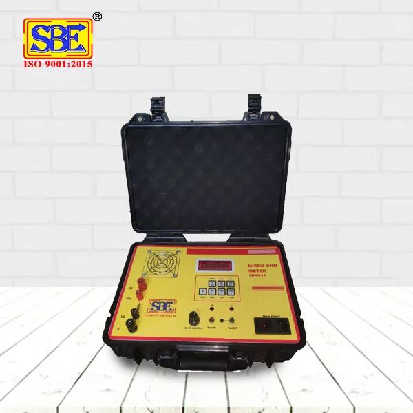
A digital micro ohm meter measures very low resistance values, the kind you find at electrical joints, contacts, and windings, using a four-terminal (Kelvin) measurement method that gives far more accurate readings than a regular multimeter. It's a must-have tool for testing electrical connections, welds, switchgear contacts, and cable joints in industries where even a tiny resistance increase can signal a serious problem. This guide breaks down what a micro ohm meter is, how it works, a step-by-step testing process for beginners, common mistakes to avoid, and answers to the questions people usually search for before buying one.
Table of Contents
- What a Digital Micro Ohm Meter Actually Measures
- Why Four-Terminal Measurement Matters
- Where Micro Ohm Testing Is Commonly Used
- Step-by-Step: How to Take a Reading
- Common Mistakes Beginners Make
- Tips for Getting Accurate and Repeatable Results
- How to Interpret What the Reading Tells You
- FAQs
What a Digital Micro Ohm Meter Actually Measures
A micro ohm meter is built to measure extremely small resistance values, often in the range of micro-ohms to a few ohms, which is far below what a standard multimeter can measure with any real accuracy. This matters because most electrical faults at joints, contacts, and connections don't show up as a complete break, they show up as a slightly higher resistance than expected, and that small increase is exactly what this instrument is designed to catch.
Think of it this way: a loose bolt on a busbar connection or a worn contact inside a circuit breaker won't stop current from flowing entirely, but it will increase resistance at that point. Over time, that extra resistance generates heat, and heat is where real damage starts. A digital micro ohm meter catches this early, well before it becomes a visible or costly failure.
Why Four-Terminal Measurement Matters
This is probably the most important concept for a beginner to understand before using the instrument.
- A regular two-terminal measurement sends current and measures voltage through the same pair of leads, which means the resistance of the test leads and connection points gets added into your reading, throwing off accuracy.
- A four-terminal (Kelvin) measurement separates the current-carrying leads from the voltage-sensing leads, so the meter measures the actual resistance of the component being tested, not the resistance of your test leads.
- This separation is what allows the instrument to measure micro-ohm level resistance with genuine accuracy, something a two-terminal setup simply can't do reliably at this scale.
If you've used a regular multimeter before and wondered why low resistance readings never seem consistent, this is exactly the limitation that four-terminal measurement solves.
Where Micro Ohm Testing Is Commonly Used
This isn't a niche instrument used by just one type of technician. It shows up across several electrical maintenance and manufacturing contexts:
- Transformer industry, checking winding resistance and connection joints during manufacturing and periodic maintenance
- Switchgear industry, testing contact resistance in circuit breakers to catch worn or pitted contacts before failure
- Panel and cable industry, verifying joint quality at busbar connections, cable lugs, and terminations
- Component manufacturing, including strain gauges, resistance thermometers, and similar precision components where resistance values need to be tightly controlled
Basically, wherever a poor electrical connection could lead to overheating, energy loss, or equipment failure, micro ohm testing tends to be part of the regular inspection routine.
Step-by-Step: How to Take a Reading
For someone using a digital micro ohm meter for the first time, here's a straightforward sequence to follow:
- De-energise the equipment being tested and confirm it's safe to work on, resistance testing should never be done on live circuits.
- Clean the test points thoroughly, dirt, oxidation, or grease at the contact surface can throw off your reading before you even start.
- Connect the current leads to the outer terminals of the connection or component being tested.
- Connect the voltage sensing leads to the inner terminals, closer to the actual point being measured, this is the key part of the four-terminal setup.
- Ensure firm, clean contact at every connection point, loose or corroded probe contact is one of the biggest sources of inaccurate readings.
- Take the reading and note it down, along with the test point identification, since you'll likely want to compare this against future readings.
- Repeat at multiple points if testing a larger system, like several joints on a busbar or multiple breaker contacts, rather than relying on a single reading.
Following this sequence consistently is what actually makes the difference between a reliable test result and one that leaves you second-guessing the numbers.
Common Mistakes Beginners Make While Using a Digital Micro ohm Meter
A few errors show up repeatedly when people are new to this kind of testing.
- Skipping the cleaning step before connecting probes, which introduces resistance that has nothing to do with the actual component
- Loose probe contact, especially with spring-loaded or clamp-type probes that aren't seated firmly enough
- Testing on energised equipment, which is both a safety risk and something that produces unreliable readings anyway
- Not recording ambient temperature, since resistance values can shift slightly with temperature, and this matters when comparing readings taken months apart
- Comparing readings across different test setups without accounting for lead length or connection method, which can introduce small but meaningful variation
Most of these come down to rushing the setup rather than any complexity in the instrument itself, slowing down slightly at the connection stage solves the majority of accuracy issues.
Tips for Getting Accurate and Repeatable Results
A few practical habits go a long way toward getting readings you can actually trust and compare over time.
- Always test at a similar ambient temperature when comparing historical data for the same equipment
- Keep a consistent test point marking system, so repeat tests are measuring the exact same location each time
- Allow the instrument to stabilise for a moment before noting the final reading, rather than recording the first number that appears
- Maintain your test leads and probes, worn or damaged leads introduce resistance that isn't part of the actual measurement
- Where possible, take readings as part of a routine maintenance schedule rather than only when a problem is already suspected
Building these habits early makes the difference between occasional troubleshooting and a genuinely useful preventive maintenance practice.
How to Interpret What the Reading Tells You
Getting a number on the display is only half the job, knowing what it means matters just as much.
- A resistance reading that's noticeably higher than similar test points on the same equipment usually signals a loose, corroded, or worn connection
- Trending upward over successive tests at the same point, even gradually, is often an early warning sign worth investigating before it becomes a failure
- Manufacturer specifications or industry standards usually provide an acceptable resistance range for specific components, comparing your reading against this range gives context to an otherwise isolated number
Rather than treating each reading in isolation, the real value of micro ohm testing comes from tracking these numbers over time and catching gradual changes before they turn into unplanned downtime.
Choosing a Reliable Instrument
Getting consistent, trustworthy readings depends a fair bit on the build quality and calibration accuracy of the instrument itself, not just correct testing technique. S.B. Electrotech manufactures digital micro ohm meters with true four-terminal measurement, used across transformer, panel, cable, and switchgear industries for contact resistance testing and related applications.
FAQs
1. What is the difference between a micro ohm meter and a regular multimeter?
A regular multimeter uses two-terminal measurement, which isn't accurate for very low resistance values since lead resistance gets included in the reading. A micro ohm meter uses four-terminal (Kelvin) measurement, separating current and voltage sensing leads to give accurate readings at the micro-ohm level.
2. Why is contact resistance testing important in switchgear and transformers?
Rising contact resistance at a joint or connection generates heat over time, which can lead to equipment failure if left unchecked. Regular micro ohm testing catches this early, well before it becomes a visible fault or causes unplanned downtime.
3. Can a digital micro ohm meter be used on live circuits?
No, resistance testing should always be done on de-energised equipment. Testing live circuits is both a safety hazard and produces unreliable readings, since current flowing through the circuit interferes with the measurement.
4. What causes inaccurate readings on a micro ohm meter?
Common causes include dirty or oxidised test points, loose probe contact, worn test leads, and not accounting for ambient temperature when comparing readings over time. Most inaccuracies trace back to setup issues rather than the instrument itself.
5. How often should micro ohm testing be done on electrical equipment?
This depends on the equipment and its criticality, but many facilities include it as part of routine preventive maintenance schedules, often annually or during scheduled shutdowns, rather than waiting until a fault is already suspected.
6. What is considered a normal resistance reading on a micro ohm meter?
There's no single universal number, acceptable resistance varies by component type and manufacturer specification. The more useful approach is comparing readings against similar test points on the same equipment and tracking changes over successive tests.