
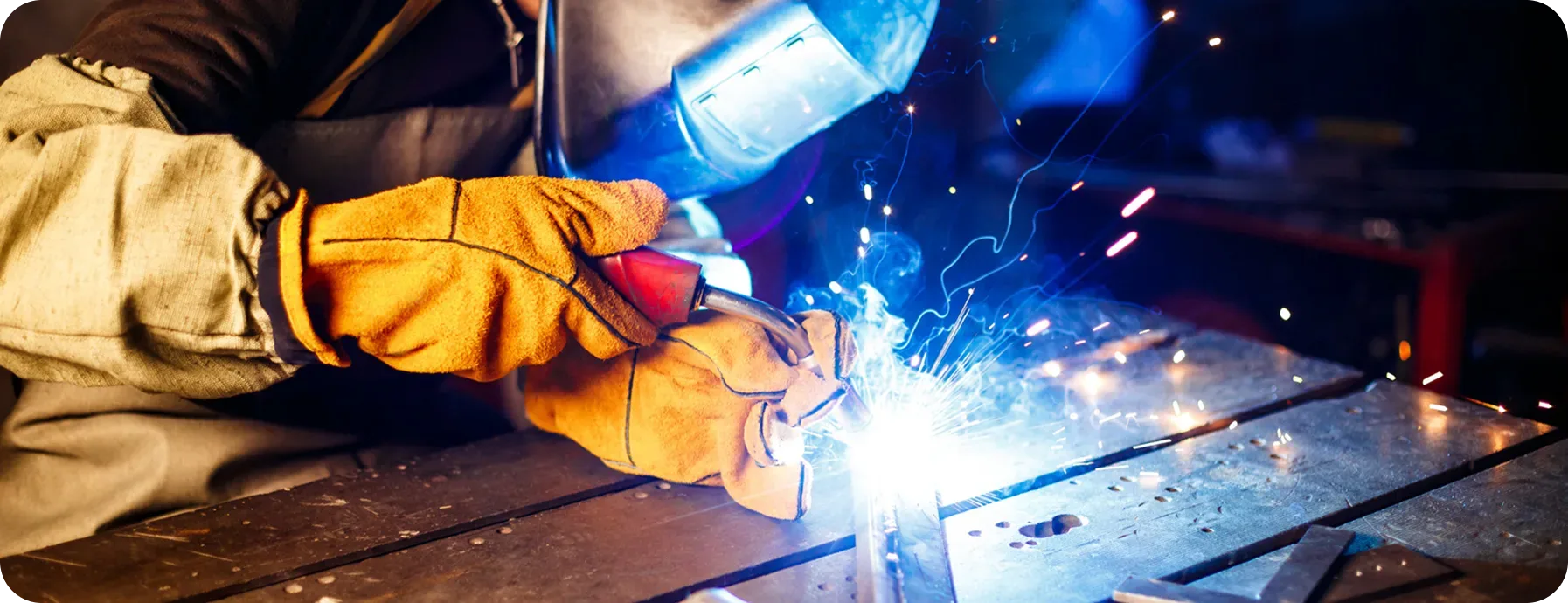
Designing a successful stainless steel sheet metal part requires more than defining its final dimensions in CAD. Engineers must consider how the material will behave during cutting, bending, welding, finishing, and assembly. Material thickness, bend geometry, tolerances, feature placement, and surface requirements can all influence whether a design moves smoothly through production.
Effective stainless steel part design connects engineering requirements with practical manufacturing capabilities. Considering fabrication constraints early can reduce unnecessary operations, limit redesigns, and make it easier to achieve repeatable results when production quantities increase.
What Material Thickness is Appropriate for the Part?
Material thickness affects strength, weight, forming requirements, welding behavior, and overall manufacturability. A thicker sheet can provide greater rigidity, but it also requires more forming force and may affect achievable bend geometry. Thinner material reduces weight but can be more susceptible to distortion during forming and welding.
Engineers should select thickness based on the component's functional requirements rather than assuming more material automatically produces a better part.
Consider expected loads, unsupported spans, fastening points, weld locations, and how the component interacts with surrounding parts. Also consider standard material availability, since unusual thicknesses can complicate sourcing and production planning.
How Does Stainless Steel Affect Bend Radius?
Stainless steel behaves differently from softer sheet metals during forming. Its strength and tendency to work harder mean you need to consider the bend radius carefully.
Attempting to form a bend that is too tight for the selected grade and thickness can increase the risk of cracking, excessive deformation, or inconsistent results. Stainless steel also experiences springback after forming pressure is removed. Fabrication tooling and bend calculations must account for this behavior.
Instead of specifying the smallest possible bend radius, engineers should establish radii that are compatible with the material, thickness, tooling, and required geometry.
Using consistent bend radii across a component can also simplify tooling requirements and make repeat production easier.
How Should Holes and Features Be Positioned Near Bends?
Holes, slots, cutouts, and other features placed close to bend lines can distort during forming. As the material stretches and compresses around the bend, nearby features may elongate, shift, or lose their intended geometry.
Therefore, maintain adequate clearance between a bend and adjacent features. The appropriate distance depends on material thickness, bend radius, feature size, and forming method.
If a feature must be located close to a bend for functional reasons, engineers should discuss the requirement with the fabricator before finalizing the drawing. You may need a different production sequence, relief feature, or secondary operation.
Planning feature placement early is usually easier than correcting distorted holes after forming.
How Tight Should Fabrication Tolerances Be?
Tolerances should reflect how the finished component functions within the larger assembly. Dimensions controlling alignment, fit, sealing, or mating interfaces may require tighter control. Other dimensions may function properly with standard fabrication tolerances.
Applying precision machining tolerances to every dimension on a fabricated sheet metal component can create unnecessary manufacturing difficulty. Tight requirements may increase setup time, inspection needs, secondary processing, and production cost without improving performance.
For effective sheet metal fabrication, engineers should distinguish critical dimensions from noncritical ones.
Drawings should clearly communicate where dimensional control is essential while allowing reasonable manufacturing variation elsewhere.
How Does Part Geometry Affect Forming?
Part geometry determines how easily a component can be formed and whether standard tooling can access each bend.
Deep flanges, closely spaced bends, narrow channels, enclosed shapes, and complex return bends can create tooling interference. A bend that appears straightforward in a CAD model may be difficult to produce because another section of the part blocks press brake tooling.
The sequence of bends also matters. Some geometries allow individual bends to be formed easily but become inaccessible after earlier bends are completed.
Engineers should therefore evaluate not only the final geometry but also how the component will reach that geometry through successive fabrication operations.
Simplifying geometry or adjusting flange dimensions can sometimes eliminate additional tooling or secondary operations.
When Should Welding Be Considered During Design?
Consider welding during design, not after individual pieces have already been defined.
Weld locations affect joint accessibility, distortion, strength, finishing, and assembly sequence. A welder or automated welding system needs sufficient access to create the required joint. The component must also tolerate the heat introduced during welding.
Thin stainless steel sheet metal can be particularly sensitive to heat-related distortion. Joint design, weld length, sequence, and fixturing may therefore influence dimensional stability.
Engineers should also consider whether a welded assembly can be simplified. In some cases, changing a formed component's geometry can reduce the number of separate pieces and welds required.
How Does Surface Finish Affect Fabrication Planning?
Surface finish should be specified before production because it can influence material sourcing, handling, welding, grinding, and final finishing.
A component intended for a visible application may require a consistent brushed or polished appearance. Scratches acceptable on a concealed industrial bracket may be unacceptable on an exposed enclosure or equipment panel.
Finish direction can also matter when several parts are assembled side by side.
If welds must be blended into surrounding surfaces, communicate that requirement on the fabrication drawing. Protective films and careful handling may also be necessary during cutting and forming.
Defining these expectations early allows the fabricator to plan the entire process around the required final surface condition.
How Can Engineers Reduce Unnecessary Manufacturing Complexity?
One of the most useful questions during design review is whether every feature serves a functional purpose.
Additional bends, unusually shaped cutouts, small tabs, multiple weldments, difficult corner details, and unnecessarily tight tolerances can add operations to a part. Each additional operation introduces production time and another opportunity for variation.
Design simplification does not mean removing necessary functionality. Instead, engineers can look for opportunities to standardize bend radii, reduce separate pieces, simplify cut geometry, improve tool access, and eliminate features that do not contribute to the component's function.
These improvements matter most when a design moves from prototype quantities to recurring production.
What Information Should Be Included in Fabrication Drawings?
Clear drawings reduce ambiguity between engineering intent and shop floor execution. A complete drawing should communicate the information required to manufacture and inspect the part without forcing production teams to make assumptions.
Depending on the project, important information may include:
- Stainless steel grade and material thickness
- Overall dimensions and critical tolerances
- Bend angles and bend requirements
- Hole, slot, and cutout dimensions
- Weld locations and applicable weld requirements
- Surface finish specifications
- Grain or finish direction where relevant
- Hardware and assembly requirements
- Critical inspection dimensions
- Revision information
Drawings should also distinguish functional requirements from general reference information. Clear documentation becomes increasingly important when you manufacture the same component repeatedly.
Quick Answers to Stainless Steel Sheet Metal Design Questions
Does stainless steel require special consideration when bending?
Yes. Evaluate material grade, thickness, bend radius, springback, and tooling when establishing bend geometry.
Should every dimension have a tight tolerance?
No. Tight tolerances are most useful where dimensional variation affects fit, function, alignment, or assembly.
Can holes be placed directly next to bends?
Features positioned too close to bend lines may distort during forming. Establish appropriate clearance based on the part geometry and fabrication method.
Should surface finish be specified before fabrication?
Yes. Finish requirements can affect material handling, forming, welding, grinding, and final processing.
When should a fabricator review a sheet metal design?
Fabricator input is most useful before the design is released for production, particularly for complex formed or welded components.
Designing Stainless Steel Sheet Metal Parts for Reliable Production
Effective stainless steel part design requires engineers to consider how material properties and component geometry interact with real fabrication processes. Thickness, bend radii, feature placement, tolerances, welding, surface finish, and tooling access can all influence the final production outcome.
Designing for sheet metal fabrication from the beginning helps connect engineering intent with manufacturability. When manufacturers address these considerations before drawings reach the shop floor, they have a clearer path to consistent components and can move designs from prototype quantities to reliable repeat production. Contact us.
People Also Ask
What should engineers consider when designing stainless steel sheet metal parts?
Engineers should consider material grade and thickness, bend radius, tolerances, feature placement, welding, surface finish, and assembly requirements.
Why is bend radius important in stainless steel sheet metal design?
A suitable bend radius helps account for material behavior during forming and reduces the risk of cracking, distortion, and inconsistent bends.
How close can holes be to a bend in sheet metal?
Required clearance depends on material thickness, bend radius, feature size, and forming method. Features placed too close may distort during bending.
Why should tight tolerances be limited in sheet metal fabrication?
Unnecessarily tight tolerances can increase manufacturing and inspection requirements without adding functional value.
What information should a stainless steel fabrication drawing include?
Drawings should clearly identify material, thickness, dimensions, critical tolerances, bends, welds, surface finish, hardware, and relevant inspection requirements.