
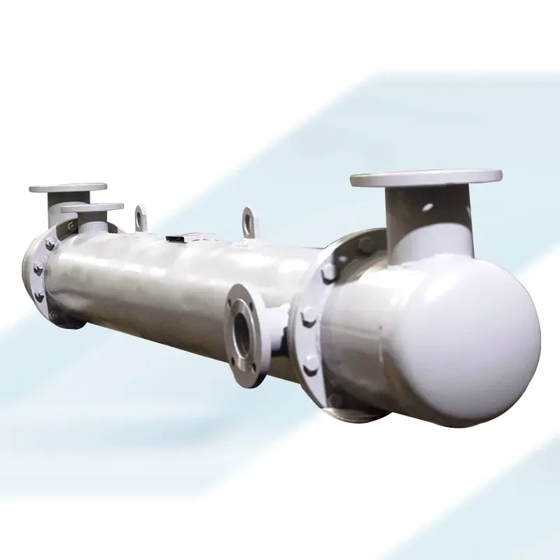
Overview - Take one fluid that needs cooling and another that can absorb that heat, keep them physically apart so they never mix, and pass heat between them through a wall of metal tubes. That is the whole idea behind a shell and tube heat exchanger, and it is why this design has stayed the standard choice across chemical plants, refineries, and power stations for decades. The basic principle has not changed much in over a century, even as materials and manufacturing methods have moved forward, which says something about how well the original concept actually works. This blog covers the basic parts, how heat actually moves between the two fluids, and where this type of exchanger is used.
This blog covers:
- Introduction
- Basic Components: Shell, Tubes, and Tube Sheets
- How Heat Actually Transfers Between the Two Fluids
- Tube Arrangement and Flow Patterns
- Common Applications
- Materials Used and Why They Matter
- Frequently Asked Questions
Introduction
A shell and tube heat exchanger does one simple job: move heat from one fluid to another without letting the two fluids actually touch or mix. One fluid runs through a bundle of tubes, the other flows around those tubes inside a larger outer shell, and heat passes through the tube walls from the hotter fluid to the cooler one.
This basic setup has been used in industry for a very long time, and it is still one of the most common heat exchanger types built today, mainly because it is simple to build, easy to maintain, and works well across a wide range of temperatures and pressures.
Basic Components: Shell, Tubes, and Tube Sheets
Every shell and tube heat exchanger is built around three main parts, and understanding what each one does makes the whole design much easier to follow.
The shell is the large cylindrical outer casing that holds everything together, and one fluid flows through the space inside the shell but outside the tubes.
The tubes themselves sit inside the shell in a tightly packed bundle, and the second fluid flows through the inside of these tubes.
Tube sheets are flat plates at each end of the shell, drilled with holes to hold the tubes in place and keep the two fluids properly separated from each other, so the fluid inside the tubes and the fluid inside the shell never actually mix.
Tubes can be straight, running the full length of the shell, or U-shaped, bending back on themselves, which changes how the unit handles thermal expansion and how it can be cleaned or serviced later.
How Heat Actually Transfers Between the Two Fluids
Heat moves through a shell and tube heat exchanger the same basic way heat moves through any solid wall, from the hotter side to the cooler side, through the metal of the tube itself.
As the hot fluid flows on one side of the tube wall and the cool fluid flows on the other, heat passes through the metal by conduction, and the temperature difference between the two fluids is really what drives this transfer.
A larger surface area, meaning more tubes or longer tubes, gives heat more room to pass through, which is why capacity and tube count scale together across different sizes of exchanger.
Smooth fluid flow on both sides also matters, since turbulence or poor flow distribution can create pockets where heat transfer is much less efficient than the rest of the unit, reducing overall performance even if the exchanger looks correctly sized on paper.
Tube Arrangement and Flow Patterns
Tubes inside a shell and tube heat exchanger are not just packed in randomly; the arrangement affects how efficiently the unit actually performs.
Tubes can be arranged in different patterns, triangular, square, or rotated square layouts being common, and this choice affects both how much surface area fits into a given shell size and how easily the shell-side fluid flows around the tubes.
Flow direction also matters; fluids can run parallel to each other in the same direction, counter to each other in opposite directions, or in a cross-flow arrangement, and each pattern changes how much heat actually transfers for a given size of unit.
Baffles, plates positioned inside the shell, direct the shell-side fluid to flow across the tube bundle rather than straight through, which improves heat transfer and also helps support the tubes against vibration caused by fluid flow.
Common Applications
A shell and tube heat exchanger shows up across a wide spread of industries, largely because the design handles high-pressure and high-temperature applications reliably.
- Refrigeration systems, for condensing and evaporating refrigerant
- Sewage treatment plants, for process heating and cooling needs
- Oil refining, handling the heavy thermal loads involved in crude processing
- Petroleum refineries, across various stages of the refining process
- Natural gas processing, where temperature control affects product quality
- Power generation plants, for cooling and condensing steam and process fluids
- Chemical processing plants, wherever a process needs controlled heating or cooling
Materials Used and Why They Matter
Material choice affects how long a shell and tube heat exchanger actually lasts, and this decision depends heavily on the fluids being handled and the conditions the unit operates under.
A stainless steel shell and tube heat exchanger is a common choice specifically because stainless steel resists corrosion well, which matters directly in applications involving aggressive chemicals or fluids with high moisture content.
Other materials, including various grades of carbon steel or specialized alloys, get used depending on the specific fluid, temperature, and pressure involved, since a material suited to one chemical process might corrode quickly in another.
Robust construction overall, not just material choice, decides how well the shell and tube heat exchanger holds up to daily industrial use, since a well-built exchanger with a properly supported tube bundle and solid tube sheets lasts considerably longer under continuous operation than one built to a lower standard.
Getting the material specification wrong at the start is one of the more expensive mistakes in this category, since replacing a corroded tube bundle years later almost always costs more than choosing the right material the first time.
Conclusion
A shell and tube heat exchanger has stayed the standard choice for over a century because the basic idea, keeping two fluids apart while passing heat through a wall of tubes, simply works, across a wide range of temperatures, pressures, and industries. Getting the details right, tube arrangement, flow pattern, and especially material selection, is what decides whether that reliability actually holds up over years of continuous operation.
Choosing the wrong material to save on upfront cost is a mistake that shows up later as a corroded tube bundle and an expensive replacement. Matched properly to the fluids and conditions involved, this design remains one of the most dependable ways to move heat industrially.
Frequently Asked Questions
What is the main advantage of a shell and tube heat exchanger over other heat exchanger types?
It handles high pressure and high temperature applications reliably, and its relatively simple construction makes it easier to clean, inspect, and repair compared to some more compact heat exchanger designs.
Can straight tubes and U-shaped tubes both be used in the same application?
Generally, the choice depends on the specific application. Straight tubes are often easier to clean, while U-shaped tubes handle thermal expansion more naturally and can be a better fit where the temperature difference between the two fluids is significant.
Why does tube arrangement matter for how well the exchanger performs?
The specific pattern tubes are arranged in such a way that affects how much surface area fits within a given shell size and how the shell-side fluid flows around the tube bundle, both of which directly affect how efficiently heat actually transfers between the two fluids.
Is stainless steel always the best material choice for a shell and tube heat exchanger?
Not always, stainless steel offers strong corrosion resistance and suits many chemical and high-moisture applications, but the right material always depends on the specific fluids, temperatures, and pressures the exchanger will actually operate under.
Manufacturers such as Abe & Hex India Private Limited, based in Ghaziabad, Uttar Pradesh, and building these exchangers since 2009, produce units in a range of sizes, materials, and configurations suited to cooling, condensing, and heating applications across chemical processing, refining, and power generation industries.