A reading can look normal and still be wrong for the job. That is the quiet risk behind many thermal decisions in medical research, industrial processing, microwave testing, and field-heavy environments. A sensor may respond to the surrounding field, collect noise, or change the very condition it is supposed to measure. That is why more teams now compare fiber optic temperature sensors with older sensor approaches before they lock in a process, a test method, or a validation plan.
When a team cannot trust temperature data, every later choice weakens. Power settings, dwell time, controller logic, safety margins, and quality checks rest on a number that may be wrong. In environments shaped by RF, microwave, magnetic, or high voltage fields, the measuring method becomes part of the process itself.
Key Takeaways
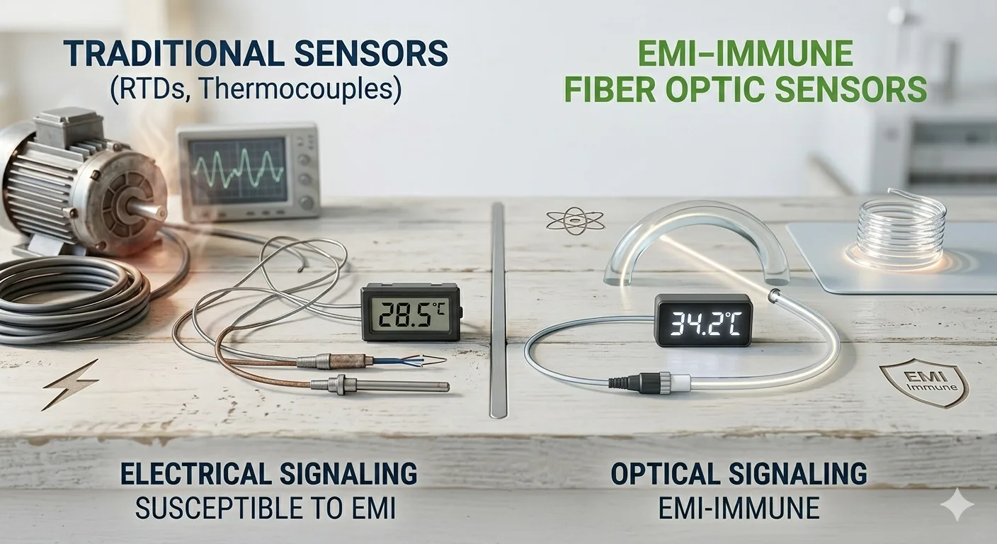
- Traditional sensors can struggle when strong fields, metal sensitivity, or noise interfere with the reading.
- Optical sensing is presented on the source pages as a better fit in electrically harsh conditions.
- Good sensor selection depends on the application, the environment, and the control goal, not only on the temperature range.
- Calibration, placement, and realistic test conditions matter as much as the sensor category.
In simple terms, the value of fiber optic temperature sensors is that they measure with light instead of relying on metal conductors at the sensing point. That changes what happens in environments where ordinary sensors may heat up, drift, create artifacts, or collect interference.
Why Do Traditional Sensors Struggle
Traditional temperature sensors work well in many ordinary settings. But the source material repeatedly shows where they begin to lose their edge. In MRI environments, metal-based probes can heat up, conventional metal cables can create artifacts, static magnetic fields can cause temperature shifts, and RF fields can induce noise into the reading.
The same pattern appears outside MRI. In wireless charging systems, the source pages explain that rapid industrial wireless power transfer creates very strong electromagnetic fields that would induce heat in normal probes. In microwave and RF component testing, conventional metal sensors were heating up from strong fields, which is one reason optical probes were used instead.
What Makes Optical Sensors Different
The technology page straightforwardly explains the principle. Fluorescent material emits light after excitation, and the system reads temperature by determining the time behavior of that material. The site also states that one significant advantage over competing sensing technologies is inherent immunity to electromagnetic noise and interference because no metal conductors are acting as antennae to transmit current and voltage.
That difference matters more than it may seem at first glance. The reading is based on optical behavior, which makes fiber optic temperature sensors especially useful in places where electrical or metal-based sensing can become unstable, noisy, or intrusive.
The source pages also point to practical strengths such as contact sensing, digital and analog outputs, fast response, robust optical fiber for easier handling, and suitability for high voltage, high RF, microwave, and electromagnetic fields.
Where Fiber Optic Temperature Sensors Fit
The source pages connect these systems to MRI and related research, microwave heating, wireless charging, microwave component testing, surgical environments, material process heating, and medical monitoring. That broad spread matters because it shows the decision is not about one industry. It is about one recurring problem.
That recurring problem is measurement under stress. In MRI, the field itself can disrupt conventional approaches. In industrial heating, the process may need live temperature feedback while AC, RF, or microwave energy is present. In component testing, taking a cover off for an infrared check can change airflow and magnetic behavior, which means the test condition no longer matches real use. In wireless charging, normal probes can be heated by the field they are trying to monitor. Fiber optic temperature sensors are valuable because they address that shared problem from the sensing side.
That is why fiber optic temperature sensors are often chosen for the application. The heating page shows that probe selection may depend on range, size, response time, durability, cleaning methods, bend radius, stiffness, biocompatibility, and required length.
What Happens During Real Use
In real use, fiber optic temperature sensors matter when the process turns on. The heating page explains that optical probes are used in AC, RF, and microwave fields for heating, drying, and process applications, and that the electronics can provide digital output or analog output for controllers, programmable logic controllers, or heating units.
The same page adds another useful point. Materials do not behave the same way throughout a heating cycle. Moisture content changes. Dielectric properties can shift at different temperatures. Placement, spacing, belt speed, food load, and tray properties can all shape heating behavior. That is one reason fiber optic temperature sensors can support better decisions in process development and troubleshooting.
How Should Teams Choose Well
A practical framework is Environment, Access, Control, Verification. Each part keeps the discussion tied to the real job instead of a generic preference list.
- Environment. Ask what surrounds the sensor. Is there RF energy, microwave energy, magnetic influence, high voltage, or tight geometry that could affect a traditional approach?
- Access. Ask where the temperature actually matters. Is it inside a component, near a charging coil, in a phantom, or inside a moving process where surface readings are not enough?
- Control. Ask how the measurement will be used. Will the reading guide a controller, validate a simulation, or help refine power level, pulse rate, or placement?
- Verification. Ask how the setup will be confirmed. The calibration page describes SI traceable calibration, metrology well calibration, additional liquid calibration for biological or chemical simulation, and an annual cycle, with a third-party ISO 17025 path typically used for FDA submissions.
Which Sensor Fits Which Job
This comparison pulls together the recurring use cases described across the source pages.
Measurement SituationTraditional Approach Often Works WhenOptical Approach Helps Most WhenCommon MistakeGeneral plant checksThe area is quiet and easy to accessStrong fields or noise are presentChoosing by habit aloneMRI-related testingRarely ideal near active fieldsMetal cannot be tolerated, and artifacts matterIgnoring the field-induced errorMicrowave component testingOpen-air checks may help with early screeningThe real condition needs cover on testingTrusting altered test conditionsWireless charging evaluationLimited when coils generate strong fieldsCoil temperature must be measured near the active power transferAssuming any probe near the field is acceptableProcess heating and dryingSurface checks may help with simple tasksControl depends on live internal or contact temperatureMeasuring the easiest point instead of the right oneThe table does not dismiss traditional sensors. It shows that context decides the winner.
What Do Teams Often Miss
The first mistake is treating all temperature sensing as basically the same. It is not. A stable reading in a quiet environment does not guarantee a stable reading in a field-rich environment. The MRI and component testing pages are clear on this. Metal-based approaches can heat, shift, create artifacts, or collect noise, while optical probes are presented as immune to the problematic fields involved there.
The second mistake is testing under conditions that are easier to observe but less realistic. The component testing page explains that high-power ferrites and similar parts are often checked first with infrared when the cover is off, and the area is visible. But taking the cover off can change the magnetic field and add air cooling that may not exist when the cover is on.
A Familiar Lab Floor Scenario
Imagine a team trying to improve a heating process for a sensitive material. Early trials look good. Then larger runs bring disagreement. One sensor path says the process is stable. Another observation suggests hidden hot spots. The team loses time arguing over equipment instead of learning from the data. This is a familiar scenario, not a formal case study, but it happens for a reason. Teams often ask whether the sensor reads temperature. The better question is whether it reads temperature accurately in that environment, at that location, under that field condition, and for that control goal.
Why This Decision Matters More
This decision matters because measurement quality shapes process quality. New Jersey reported 9,800 manufacturing establishments in 2024, which hints at the scale of operations that depend on repeatable process control and credible thermal data. When temperature information is weak, quality margins shrink, and troubleshooting slows down.
In practical terms, fiber optic temperature sensors do not replace every traditional option everywhere. They matter most where ordinary sensing becomes part of the problem. That is why the source pages keep returning to MRI, microwave heating, RF testing, wireless charging, high voltage, and other conditions where interference or metal behavior can undermine a conventional approach.
Where Better Measurement Decisions Begin
Traditional sensors are still valuable in many everyday tasks, but they are not automatically the right answer for every demanding application. When the environment itself can change the reading, the sensor choice becomes strategic.
That is where BioTemp4Life fits naturally in the conversation. The company’s source pages focus on advanced temperature measurement support for MRI, microwave heating, wireless charging, component testing, medical research, and industrial process applications, where fiber optic temperature sensors can offer a more dependable path than conventional metal-based approaches. For teams making informed decisions in hard environments, that kind of application-driven guidance can make the difference between a reading that looks acceptable and one that can actually be trusted.
FAQs
How can this provider help with a difficult measurement problem?
It focuses on application support for demanding environments where conventional approaches may struggle with field effects, noise, or access limitations.
What services are most relevant here?
System selection support, application guidance, and calibration pathways matter most.
What makes a good sensor choice?
A good choice matches the environment, the measurement location, the control goal, and the verification plan.
What are the best practices for reliable thermal checks?
Measure under real operating conditions, keep placement consistent, and verify the setup before making larger decisions on the data.
When should a team hire professional support?
When the environment is electrically harsh, the setup is hard to access, or current readings do not match real performance.