The default answer to a wideband RF run used to be coax, until the run gets long enough that loss stops being a nuisance and becomes the design constraint. Fiber removes that constraint but not the engineering: a photonic link is still an analog circuit, and it behaves only as well as the three devices at its edges allow.
Read a link datasheet by asking which conversion each number belongs to. Gain, compression, noise figure and bandwidth all trace to one of three interfaces, and that trace tells you which part to change when the link misses its target.
Three Conversions, One Budget
Every link runs the same sequence: current becomes light, light travels through fiber, light becomes current again. The middle step is close to ideal — fiber adds delay and a predictable loss, nothing more. The first and last steps decide performance.
That division is commercial as well as technical. The DFB laser and its driver set the noise floor and the linearity ceiling. The high speed photodetector sets the output level and the compression point. Fiber length sets the loss between them. Treat the three as one budget and the design converges; treat them as three shopping decisions and the link ends up noisy or expensive.
The DFB Laser: A Stable Source, Not a Generic Light Bulb
The DFB laser is not a generic light source. A distributed feedback laser etches a periodic grating along the active region, so the cavity selects a single longitudinal mode instead of the comb a Fabry-Perot cavity permits. That single-mode behaviour buys two things in analog transmission: mode partition noise leaves the link budget, and the wavelength stays put when drive current and case temperature move.
NEON's high-speed DFB DML laser series shows what to look for: 1310 nm and 1550 nm variants, 18 GHz bandwidth, low threshold current, high output power, and case temperature from -40 to 70 degrees Celsius. Wavelength stability keeps dispersion predictable over long spans, which is why 1550 nm parts pair with dispersion-managed fiber.
Linearity is the second property to interrogate. A DFB laser that compresses early turns a clean two-tone test into third-order products no receiver gain can remove. Ask for the input third-order intercept and the 1 dB compression point at the bias current you will actually use, not at a laboratory optimum.
The Direct Modulation Transmitter: Simplicity With a Price List
A direct modulation transmitter puts the RF signal straight onto the laser bias current. There is no external Mach-Zehnder device, no bias controller hunting quadrature, and no polarization loss to track as the enclosure warms. The module is smaller, cheaper and more efficient, and below roughly 18 GHz it is often the right answer.
The price is chirp. Modulating current changes carrier density, which changes refractive index, so the emission wavelength shifts during every transition. Over a few hundred metres of fiber this is tolerable; over kilometres, chirp interacts with dispersion and distortion grows with distance. Every direct modulation transmitter should be specified at the span length you will actually deploy.
Linearity is governed by the laser's power-current curve and the chosen bias point. Too near threshold, the waveform clips; too high, relaxation oscillation overshoot appears and power is wasted as heat. Request composite second-order and triple-beat figures, plus a link gain that already includes the detector's responsivity.
The High Speed Photodetector: Where Margin Disappears
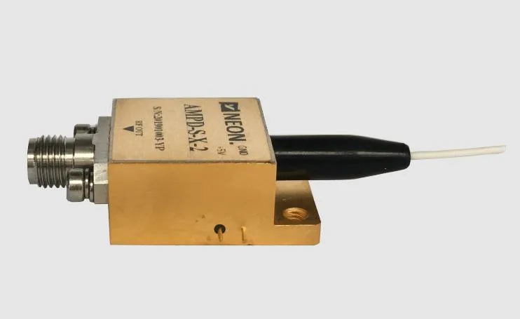
At the far end an InGaAs photodiode converts light back into current. Three parameters dominate: responsivity, saturation optical power and bandwidth. NEON's InGaAs high speed photodetectors quote at least 0.9 A/W at 1310 nm and 1550 nm, saturation optical power of 5 to 13 dBm depending on model, dark current below 10 nA, and bandwidth to 30 GHz. Hermetic sealing, DC coupling, an integrated bias tee and a 50 ohm output to SMA, SMP or 2.92 mm connectors simplify integration.
Saturation deserves more attention than it receives. A detector that is merely fast will compress quietly when the optical budget is generous, and the distortion then looks like a link problem rather than a receiver problem. Pair the saturation point with launch power, then add margin for aging and connector loss. Amplified variants add 15 to 30 dB of RF gain, which can rescue a lossy link but raises the noise floor by their own noise figure.
How to Make the Three Agree
It is tempting to buy the fastest part in every column. A 30 GHz high speed photodetector behind an 18 GHz direct modulation transmitter buys nothing except noise. Set bandwidth from the actual modulation, then choose the detector to cover it with 20 to 30 percent margin. Balance gain against noise figure: RF gain at the receiver improves noise figure only when it comes before the loss.
Thermal design is part of the optical design: a laser's wavelength drifts with temperature, a detector's responsivity shifts with it, and a link that meets specification on a bench may miss it in an enclosure fifteen degrees warmer.
Antenna remoting, radar work, electronic warfare and telemetry rest on the same three conversions: a stable source, an honest transmitter and a detector out of compression.
Inside the Analog Photonic Link: Three Devices, One Budget