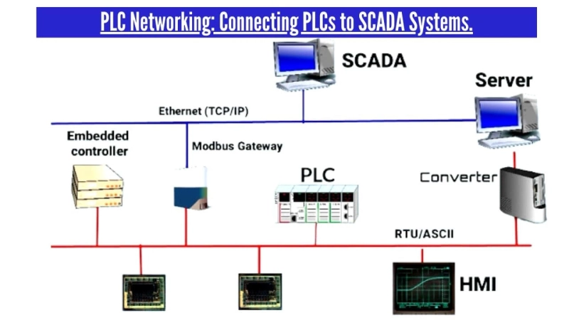
In industrial automation systems, PLCs are often connected to SCADA (Supervisory Control and Data Acquisition) systems to provide a comprehensive control and monitoring solution. While SCADA systems offer a centralized interface for operators to monitor and control the system as a whole, Allen Bradley PLCs are in charge of controlling the machinery and processes on the factory floor.
Setting up a network connection between the two systems is typically required to connect PLCs to SCADA systems. The fundamental procedures for joining PLCs to SCADA systems are as follows:
1. Determine the appropriate communication protocol:
There are a variety of communication protocols that can be used to connect PLCs and SCADA systems, including Modbus, OPC, and Ethernet/IP. Choose the protocol that is most appropriate for your system.
An industrial facility needs to monitor and control its manufacturing processes using a SCADA system coupled to many PLCs. The facility requires a communication protocol that can handle large amounts of data quickly, securely, and reliably. Ethernet/IP is a popular choice for this application because it provides fast communication speeds, supports encryption and authentication, and can handle large amounts of data.
A water treatment plant needs to monitor and control its various processes using a SCADA system connected to several PLCs located in different areas of the plant. The plant needs a communication protocol that is reliable, can handle analog signals, and supports remote monitoring and control. For this application, Modbus is frequently utilized since it is dependable, handles analog signals, and works with remote equipment across large distances.
2. Configure the network settings:
This includes configuring the IP addresses, subnet masks, and gateway settings for both the PLCs and the SCADA system. Ensure that all devices on the network are using compatible settings.
A manufacturing plant needs to connect its PLCs to a SCADA system using Ethernet/IP. Each device\'s network configuration, including its IP address, subnet mask, and default gateway, must be set up by the plant. This guarantees that the devices can talk to one another over the network.
Using Modbus TCP, a water treatment facility must link its PLCs to a SCADA system. The plant needs to configure the IP address and port number of each device to ensure that they can communicate with each other over the network. Also, the plant may need to set up virtual private network (VPN) connections to ensure that the data exchange between the two systems is safe.
3. Configure the communication settings:
This includes specifying the data exchange format and data points to be exchanged between the PLCs and the SCADA system. This may involve creating a tag database or configuring data exchange points within the SCADA system.
A power plant needs to connect its Rockwell Automation PLC to a SCADA system using OPC. The plant needs to configure the OPC server settings, such as the server name, user name, and password, in the SCADA system to ensure that it can communicate with the PLCs. Additionally, the plant may need to configure the PLC communication settings, such as the station number and communication protocol, to ensure that they are compatible with the OPC server.
A food processing factory needs to connect its PLCs to a SCADA system utilizing Modbus RTU. To ensure that each device\'s communication settings are compatible with the Modbus RTU protocol, the plant must set each one\'s baud rate, data bits, parity, and stop bits. Additionally, the plant may need to configure the SCADA system to use the correct communication driver and data format.
4. Test the network connection:
Before deploying the system in a production environment, thoroughly test the network connection to ensure that data is being exchanged correctly and reliably between the PLCs and the SCADA system.
A water treatment facility used Ethernet/IP to link its PLCs to a SCADA system. The plant must test the network connection after configuring the network and communication settings to make sure the devices are communicating properly. This can be done by using diagnostic tools, such as a network analyzer or a traffic monitor, to evaluate the network traffic and discover any faults that may be impeding communication.
A manufacturing plant has connected its 1766-L32AWA | MicroLogix 1400 PLC System to a SCADA system using Modbus TCP. After configuring the network and communication settings, the plant has to verify the network connection to confirm that the data is being sent appropriately. This can be achieved by capturing and analyzing the data being exchanged between the devices and the SCADA system using a data monitoring tool, such as a data logger or a data analyzer.
5. Monitor the system:
Once the system is deployed, monitor the network connection and data exchange to ensure that the system is operating as expected. Make adjustments as necessary to optimize system performance.
A food processing plant has connected its PLCs to a SCADA system using OPC UA. The plant needs to monitor the system to ensure that the devices are communicating correctly and that data is being exchanged accurately. This can be done by using a monitoring tool, such as a performance monitor or a health monitor, to track the performance of the network and identify any issues that may be affecting communication.
A chemical plant has connected its PLCs to a SCADA system using Modbus RTU. The plant needs to monitor the system to ensure that the data is being exchanged accurately and that the devices are responding correctly to commands from the SCADA system. The data being exchanged between the devices and the SCADA system can be captured and analyzed by using a data monitoring tool, such as a data logger or a data analyzer.


