

In 2025, the wireless ecosystem is evolving faster than ever. With 5G expanding across industries—from automotive connectivity and smart factories to immersive AR/VR—ensuring device reliability is no longer optional; it’s mission-critical. This is where the 5G OTA chamber becomes the cornerstone of advanced RF validation. As more products integrate mmWave, beamforming, and massive MIMO systems, organizations are prioritizing robust, repeatable over-the-air testing to guarantee real-world performance. Inside these specialized chambers, a blend of precision engineering, controlled RF environments, and automation makes accurate results possible.
Before diving deeper, here’s a quick snapshot of what you’ll take away from this article.
Key Takeaways
- Understand what truly happens inside a 5G OTA chamber and why its internal design directly impacts test accuracy.
- Learn the essential features—such as RF shielding, quiet zones, and advanced measurement systems—that enable trustworthy OTA performance results.
- Explore challenges organizations face in mmWave and sub-6 GHz OTA testing and how the right chamber mitigates them.
- Get actionable insights on selecting and optimizing OTA environments for reliable 5G performance testing.
- Access an FAQ section addressing practical queries about setup, calibration, chamber size, testing methodology, and more.
Why OTA Testing Matters More Than Ever
As 5G matures, devices are expected to handle higher frequencies, denser data traffic, and complex use cases. Traditional cabled testing cannot fully represent real-world behavior, especially for beamforming antennas, wearable devices, and connected vehicles. OTA (Over-the-Air) testing recreates realistic wireless conditions, ensuring antennas, radios, and integrated systems perform as intended.
This makes it essential to understand what a high-performance 5g ota chamber looks like from the inside—and which features matter most for accuracy, repeatability, and compliance with standards like 3GPP.
Key Internal Features That Ensure Reliable OTA Test Results
Reliable OTA results don’t happen by accident. They rely on a tightly engineered environment where interference, reflections, and inconsistencies are eliminated. Below are the core features that make this possible.
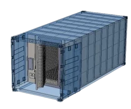
1. RF Shielding and Anechoic Material
The foundation of any 5G OTA chamber is its ability to block unwanted RF signals and create a reflection-free environment.
RF Shielded Enclosure
The chamber’s metal construction prevents external RF signals from interfering with measurements, ensuring only controlled test signals influence results.
Anechoic Absorbers
The interior walls are lined with pyramid-shaped electromagnetic absorbers. These eliminate reflections and create an “echo-free” zone—necessary for accurate antenna and RF performance characterization.
This combination ensures consistent, interference-free testing across frequencies including challenging mmWave bands.
2. High-Precision Antenna Positioning System
With 5G beamforming and directional mmWave signals, precise orientation becomes critical.
Multi-axis Positioners
Automated turntables and arm systems rotate the device under test (DUT) accurately along azimuth and elevation.
Accuracy and Repeatability
High-grade positioners achieve sub-degree, sometimes arcsecond precision, enabling reliable measurements across multiple test cycles.
Software-Driven Automation
REST APIs and advanced control software help automate sequences, reduce human error, and boost throughput—especially in production test environments.
3. The “Quiet Zone” (QZ)
The quiet zone is the most important area inside the chamber.
This is the region where the electromagnetic field is stable and meets criteria for amplitude, phase, and planarity. A well-designed QZ ensures:
- accurate radiation pattern measurements
- predictable far-field conditions using DFF or CATR
- reliable 3GPP-compliant testing
A poor QZ leads to measurement inconsistencies—one of the top challenges organizations face when defining OTA test environments.
4. Measurement Antennas and Systems
Inside every high-performance chamber are specialized antennas and RF instruments.
Probe Antennas
These calibrated antennas send and receive test signals to characterize DUT performance.
Signal Generators and Analyzers
High-frequency analyzers and generators feed the antennas through filtered RF ports. They create controlled 5G waveforms for:
- EIRP/EIS testing
- radiation pattern measurements
- TRP/TIS metrics
- MIMO and throughput performance validation
Precision here directly influences final test accuracy.
5. Advanced Measurement Techniques
Different OTA methodologies enable far-field or near-field test environments.
Direct Far-Field (DFF)
Used when space permits, ideal for large DUTs and sub-6 GHz antennas.
Compact Antenna Test Range (CATR)
The gold standard for mmWave testing.
A parabolic reflector converts spherical waves into a planar wavefront within the quiet zone, allowing far-field testing in minimal space.
Multi-Probe Anechoic Chambers (MPAC)
Perfect for MIMO, RRM, and channel emulation tests.
Multiple probe antennas emulate real-world fading conditions, enabling faster dynamic testing.
6. Rigorous Calibration
Even the perfect chamber cannot guarantee accuracy without routine calibration.
Calibration procedures:
- correct system losses
- validate probe antenna performance
- verify quiet zone uniformity
- ensure consistency across test cycles
Regular validation is crucial for long-term measurement reliability—especially when testing across multiple product revisions.
7. Integrated Software and User Interface
Modern OTA chambers rely heavily on software.
A comprehensive software suite allows you to:
- automate positioner movement
- control RF paths and instruments
- run multi-step measurements
- collect data in real time
- analyze results visually
- integrate with network simulators for advanced scenarios
Remote monitoring and customizable workflows give organizations flexibility and faster turnaround times.
Challenges OTA Chambers Solve for Modern Organizations
Organizations testing 5G devices face several pain points, including:
- external RF interference
- inconsistent measurement environments
- limited testing space for mmWave far-field requirements
- manual test processes prone to human error
- rapidly changing standards and compliance expectations
A well-engineered 5g ota chamber eliminates these obstacles, enabling scalable, repeatable, and highly accurate testing for both R&D and production workflows.
Best Practices for Choosing the Right 5G OTA Chamber
1. Start with Your Frequency and DUT Requirements
Sub-6 GHz devices need spacious QZs; mmWave requires CATR for compact precision.
2. Prioritize Repeatability
Ask vendors about validation procedures, calibration cycles, and long-term measurement stability.
3. Ensure Automation Compatibility
Robotic positioners, REST APIs, and instrument control integration significantly reduce testing time.
4. Evaluate Maintenance and Support
Complex RF environments require proactive maintenance to stay compliant.
5. Think Ahead
Choose a chamber with upgrade paths that support evolving 5G and eventual 6G requirements.
Frequently Asked Questions
1. What size OTA chamber do I need for 5G testing?
The size depends on your DUT and test methodology. Larger devices like automotive antennas require bigger quiet zones, while mobile and wearable devices fit comfortably in compact CATR-based chambers.
2. Why is the quiet zone so important in OTA testing?
A quiet zone ensures stable field distribution. Without it, amplitude and phase variations distort measurements, making results unreliable.
3. Do all 5G devices require mmWave OTA testing?
No. Only devices supporting 24 GHz and above need mmWave OTA test conditions. Sub-6 GHz devices can be tested in traditional far-field chambers.
4. How often should a 5G OTA chamber be calibrated?
Most organizations calibrate annually, but high-volume test labs may calibrate quarterly to maintain consistent results.
5. Can OTA chambers be used for Wi-Fi 7 or IoT testing?
Absolutely. Chambers supporting frequencies up to 40–50 GHz are compatible with advanced Wi-Fi and IoT standards.
6. What is the difference between DFF and CATR testing?
DFF requires long distances for true far-field conditions, while CATR uses reflectors to simulate far-field behavior in a compact space—ideal for mmWave testing.
Empower Your 5G Testing With the Right OTA Environment
As the demands of 5G continue to grow, organizations need test systems that guarantee accuracy, scalability, and future readiness. Whether you're validating a small IoT device or a sophisticated mmWave module, the internal design of your OTA chamber directly impacts your results. For teams seeking reliable, high-performance solutions, Orbis Systems offers advanced 5G OTA testing environments engineered with precision, automation, and long-term reliability in mind—helping you stay ahead in an increasingly connected world.