A Guide on How to Select a Cable Tray on the Basis of its use

What are the purposes behind choosing a particular sort of a cable tray? The architect or fashioner should choose the kind of cable tray that has the elements which best serve the task’s prerequisites.
For a couple of kinds of establishments, the National Electrical Code (NEC) indicates the cable tray type to be utilized: Single guide cables and Type MV cables should be introduced in ladder or ventilated trough cable tray.
Single guide cables and Type MV cables are not permitted to be introduced in strong base link plate [1993 NEC Section 318-3(b)].
Table of Contents
Selection Criteria
- The number of cables supported and their types
- Environmental conditions
- Corrosion susceptibility
- Cable weight
- Bending radius
- Entry and exit freedom of the cable
- Easy installation
- Can more cable trays be added?
- Amount of heat
- Support spans length
Here are the types and uses of cable trays to determine which cable tray you should select?
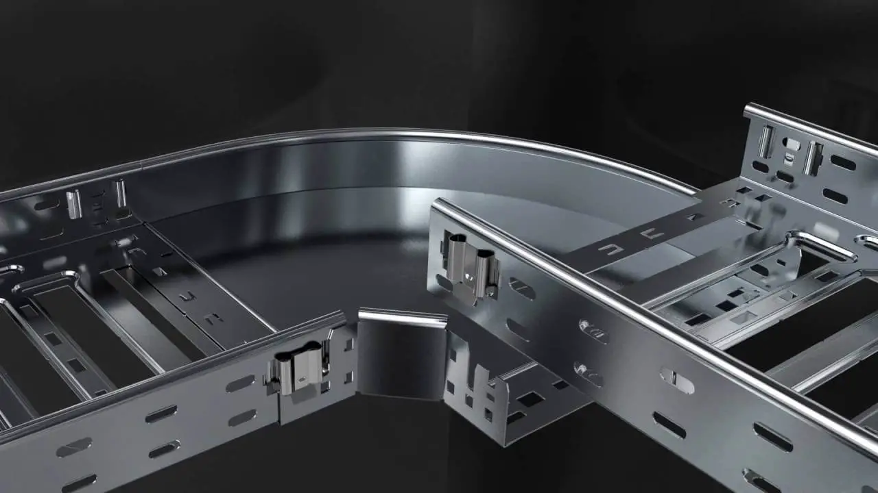
Ladder Cable Trays
Ladder cable tray is utilized for around 75% of the cable tray wiring system establishments. It is the prevailing cable tray type because of its numerous beneficial features.
- A ladder cable tray without covers allows the most extreme free progression of air across the cables. This permits the hotness delivered in the cable’s guides to successfully disseminate.
Under such circumstances, the transmitter protection in the cables of an appropriately planned cable plate wiring system won’t surpass its most extreme working temperature.
The cables won’t rashly mature because of unnecessary working temperatures.
- The rungs of the ladder cable tray give advantageous anchors to secure the cables in the non-flat cable tray runs or where the places of the cable tray should be kept up within the horizontal cable tray runs.
This capacity is an absolute necessity for single guide link establishments.
Under issue conditions (hamper), attractive powers delivered by the shortcoming current will drive the single guide cables from the cable tray on the off chance that they are not safely moored to the cable tray.
- Cable might exit or enter the stepping stool cable tray through the top or the lower part of the cable tray. Where the cables enter or leave course, the channel to cable tray braces might be introduced upstanding or altered to end conductors on the top or lower part of the cable tray side rail.
Dampness can’t aggregate in a stepping stool cable tray. Assuming cable trays are being introduced.
- Assuming that cable trays are being introduced where working space is an issue, hand access through the cable tray base might assist with working with the establishment of little width cable: control instrumentation, signal, and so on.
- The most widely recognized rung spacing for cable trays is 9 inches. This separation might be utilized to help all sizes of cables.
This dispersing is alluring for the little breadth Type PLTC and TC cables as the help distance is with the end goal that there is no noticeable hanging of the little cable between rungs.
12 or 18-inch rung dispersing offers satisfactory cable help yet the small measure of little width cable hanging between rungs might be tastefully frightful for certain establishments.
The greatest passable distance between upholds for 1/0 through 4/0 AWG single guide cable is 9 inches [1993 NEC Section 318-3(b) (1)].
Ventilated trough Cable Tray
The main motivation to choose a ventilated trough cable tray over a ladder cable tray is felt. No hanging of little cables is noticeable.
The ventilated trough cable trays offer more help to the cable than does the ladder cable tray yet this extra help isn’t huge. It does not affect the cable’s service record or life.
The ventilated trough cable tray offers more help to the cables than does the ladder cable tray yet this extra help isn’t critical. It did not affect the cable service record or life.
A ventilated tray has openings in the lower part of the cable, permitting some air dissemination around the cables, water waste, and permitting a residue to fall through the cables.
Little cables might leave the cable through the ventilation openings, which might be either spaces or openings punched in the base.
A ladder cable tray has the cables upheld by a navigation bar. We can avail these cable trays by contacting Power Engineering, the best cable tray manufacturer in Pakistan.
Solid Bottom Cable Trays
The primary justification for choosing solid bottom cable trays (with covers) is the worry of EMI/RFI safeguarding assurance for extremely delicate circuits.
A solid bottom cable tray with steel covers gives a decent level of protection in the event that there are no breaks or openings in the finished establishment.
The solid bottom cable tray system has a detriment in that dampness can develop in the cable tray.
This can be constrained by boring 1/4 inch channel openings in the lower part of the cable tray at three foot stretches (at the center and exceptionally close to the sides) in the event that the cable tray isn’t being utilized for EMI/RFI safeguarding.
A few specialists and planners indicate solid bottom cable tray (regularly with covers) in the conviction that all electrical circuits must be completely encased by metal.
The cable trays are simply supporting cables that are intended for such establishments.
Cable disappointments in cable tray runs seldom occur. Cable disappointments because of cable support issues in the cable tray are nonexistent.
Conclusion
Cable trays are a mechanical emotionally supportive network that can uphold electrical cables utilized for power dispersion, control, and correspondence.
They are the ideal answer for running huge amounts of power or data cables upward or under-floor.
